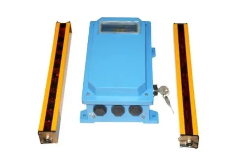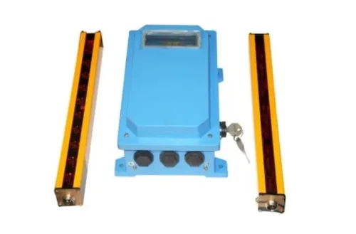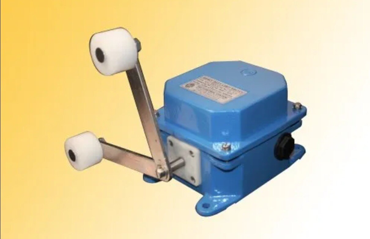
A rotary paddle level switch can report the grease reservoir condition, but it cannot confirm train presence or prove that grease reached the rail. By separating train detection, level sensing, pump operation, delivery, and control wiring, you can identify the failed stage without replacing the wrong device or leaving the pump able to run uncontrolled.
Key takeaways
- Separate train detection from reservoir level sensing before replacing components.
- A paddle switch reports one grease level point, not pump output or rail lubrication.
- Trace the signal from train detector to controller, pump, reservoir, and rail.
- Test temperature, wiring, sealing, paddle movement, and contact state before specifying a replacement.
Separate train detection from grease-reservoir level sensing
A rotary paddle level switch measures whether grease covers one fixed point inside the reservoir. Its small motor turns a paddle; when grease resists rotation, the switch changes its contact state and reports covered or uncovered. It does not measure grease volume continuously, pump output, line pressure, or lubricant at the rail.
Keep these signals separate:
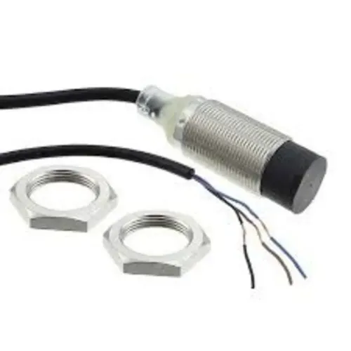
- Train detection: an inductive proximity sensor detects the metal target on a passing train and starts the lubrication cycle.
- Reservoir level: the rotary paddle level switch reports grease presence at its installed height.
- Grease delivery: pump feedback, pressure, flow, or nozzle inspection confirms that lubricant reached the rail flange.
A train sensor cannot be replaced by a level switch because the two devices answer different questions. A full reservoir can coexist with a failed train detector, while a detected train can be followed by no lubrication because the pump, hose, or nozzle is blocked.
A low-level switch also cannot establish that grease has reached the track.
For rotary paddle level switch problems in automatic rail track grease sensor systems in Mumbai, verify the physical reservoir level against the switch indication before replacing parts. Inspect the paddle for hardened grease, free rotation, mounting clearance, supply voltage, contact state, moisture, and damaged terminals.
Treat rail track grease sensor problems as separate detection, level, control, pumping, and delivery faults.
Trace the fault from train detection to the rail
Start at the event that should trigger lubrication, not at the reservoir alarm. A pump that runs proves neither train detection nor grease delivery.
1. Confirm the train-detection sensor sees the target. Check sensing distance, mounting gap, alignment, target material, supply voltage, output state, and contamination from grease, water, ballast dust, or metal debris. Inspect the cable and connector for damage. Missed or false detections identify an input problem before you examine the paddle switch.
2. Watch the controller input while presenting a valid train signal. If the sensor output changes but the PLC input does not, check the input common, terminal wiring, interposing relay, logic permissive, and lubrication-cycle timer. Review alarm delay settings; a short pulse can disappear in the control logic.
3. Command a permitted lubrication cycle and observe the pump. A silent pump points to power, fuse, drive, relay, or pump faults. A continuously running pump points to a stuck command, failed feedback, or incorrect timer logic.
4. Compare the actual grease level with the rotary paddle indication. Isolate power, remove the switch cover, inspect for hardened grease or obstruction, and confirm free paddle rotation and mounting clearance. Check supply voltage, contact state, terminals, and cable glands for moisture.
5. Prove delivery separately. Inspect pump-chamber filling, hose pressure or flow, hose blockage, frozen nozzle, nozzle alignment, and grease on the rail flange. An acceptable level cannot exclude these failures.
This sequence separates automatic rail track grease lubrication sensor faults from rail track grease sensor problems that replacing a level switch will not fix. Confirm the pump cycle reaches the rail.
Diagnose false level signals and mechanical paddle faults
A rotary paddle switch reports material at one fixed height, not the usable grease volume throughout the reservoir. A low signal can result from a genuinely uncovered paddle, incorrect contact interpretation, loss of supply, or a failed motor; a high signal can persist when grease coats the paddle after the level falls.
Check the physical level against the sensing point, then isolate power and work through these causes:
- Low level with grease above the paddle: inspect for a broken drive, seized shaft, excessive mounting clearance, open terminal, or PLC input wired to the wrong contact.
- High level with grease below the paddle: remove hardened grease, foreign material, or semi-cured lubricant from the paddle and shaft. A coating can keep the mechanism loaded, while overload protection can stop rotation and leave a persistent covered signal.
- No change during filling or draining: verify supply voltage, contact switching, shaft freedom, and clearance from the reservoir wall. A stalled mechanism, welded contact, moisture-filled gland, or PLC alarm delay can mask the change.
- Any disagreement: compare the switch state at its terminals with the PLC input indicator. This separates a mechanical fault from wiring, logic, and alarm-timer faults.
Most rotary paddle switches target dry powders and granules, not sticky rail grease. Ask a rotary paddle level switch manufacturer to confirm grease compatibility, NLGI range, temperature limits, seal design, and stall-restart behaviour. Treat these checks as automatic rail track grease lubrication sensor faults; a level signal still cannot prove that grease reached the rail.
Check installation, temperature, wiring, and outdoor exposure
Start with the physical grease level beside the indicated state. Before touching the switch, isolate its supply. A coated paddle can stay loaded after grease falls below the sensing point, producing a false-high signal; hardened grease, ballast, or foreign material can stall it.
Confirm free rotation and clearance from the tank wall, inlet pipe, and agitator.
Use this inspection sequence:
- Check the switch’s mounting depth, gasket, shaft alignment, and paddle clearance. A tilted body or paddle rubbing the tank can cause intermittent operation.
- Compare the installed grease temperature with the switch’s specified minimum and maximum. Cold grease increases drag; heat can soften grease and contaminate the shaft seal.
- Confirm the grease type and NLGI grade are compatible; do not assume a bulk-solids switch suits sticky rail lubricant.
- Inspect cable glands, conduit, junction boxes, and terminals for water, condensation, corrosion, loose conductors, or crushed insulation.
- Verify supply voltage, contact form, and the PLC input state during paddle rotation, power loss, and restart. A broken wire can look like either “low” or “normal,” depending on the circuit.
- Check the alarm delay and overload-reset behaviour before replacing the device.
| Area | Check | Misleading result |
|---|---|---|
| Mechanical | Paddle coating, obstruction, free rotation | False high or no change |
| Environmental | Temperature, moisture, grease compatibility | Drift, stall, or intermittent signal |
| Electrical | Supply, terminals, contact and PLC logic | False low or normal state |
Give these findings to a rotary paddle level switch supplier; they expose rail track grease sensor problems that a replacement alone will not fix.
Specify and test a replacement without creating a new failure
Order by the actual reservoir and control circuit, not by the phrase “level switch.” A search phrase such as rotary paddle level switch for problems automatic rail track grease sensor in mumbai does not identify the required supply voltage, contact logic, or grease compatibility.
Ask the rotary paddle level switch manufacturer or rotary paddle level switch supplier to confirm:
- Minimum and maximum temperature, grease type and NLGI grade, and whether the paddle and shaft resist that grease.
- Mounting thread or flange, insertion length, shaft and paddle material, enclosure rating, and shaft-seal construction.
- Supply voltage, SPDT contact form, contact rating, switching current, overload behaviour, stall and restart behaviour, and available replacement paddles or seals.
- The exact PLC wiring: common, normally open or normally closed contact, loss-of-power state, and required alarm response.
SAI CONTROL SYSTEM can help compare a replacement sensor’s interface with the existing rail-grease controller, but the terminal diagram remains the authority.
Test an unpowered switch with its wires removed from the PLC. Set the multimeter to continuity and record COM-NO and COM-NC states with the paddle uncovered, then rotate or cover it according to the switch design; the state must change cleanly. Do not measure resistance through a powered input.
For a live PLC test, restore the specified supply, keep hands clear of the rotating motor, and observe the input indicator while covering and uncovering the paddle. Confirm the PLC changes to the intended alarm state, and separately test cable continuity, moisture-free terminals, stall response, and alarm delay.
Never use a replacement contact state that makes a broken wire look like a full grease reservoir.
Related product
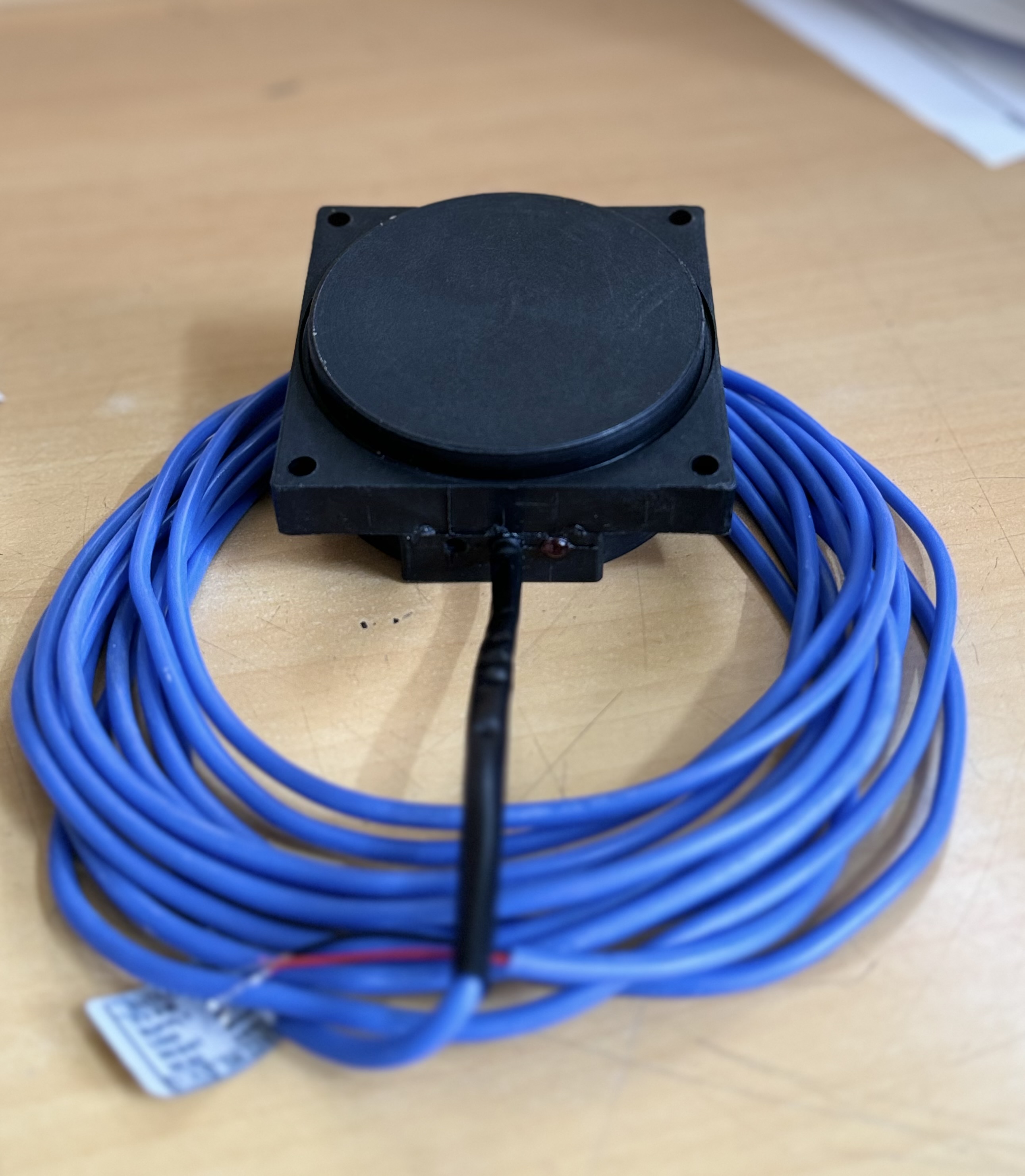 | Inductive Proximity Sensor Automatic Rail Track Grease Lubrication Sensor These sensors are used to detect passing trains, which activates the pump to deliver the correct amount of grease to the wheel flange and rail in... View product → |
Frequently asked questions
Why must train detection be separated from grease-reservoir level sensing?
Train detection starts the lubrication sequence, while a rotary paddle level switch only reports whether grease reaches one fixed point in the reservoir. Confusing these signals sends troubleshooting toward the wrong device.
How do you trace an automatic rail track grease lubrication fault?
Follow the complete path: train detector, controller, pump, reservoir level signal, grease line, applicator, and rail. Confirm each stage changes state and delivers grease before replacing the level switch.
What causes false level signals from a rotary paddle switch?
Check grease buildup, hardened lubricant, a blocked or bent paddle, incorrect mounting depth, motor failure, contact wear, loose wiring, condensation, and water ingress into the housing.
What should you check before installing a replacement level switch?
Match the switch to the grease temperature, outdoor enclosure, supply voltage, contact rating, mounting thread, paddle clearance, and required fail-safe contact state. Bench-test paddle rotation and contacts before commissioning.