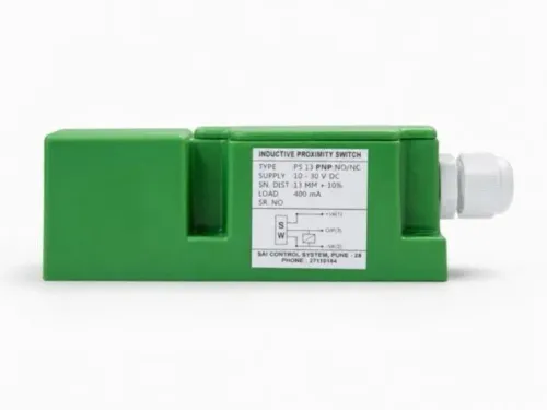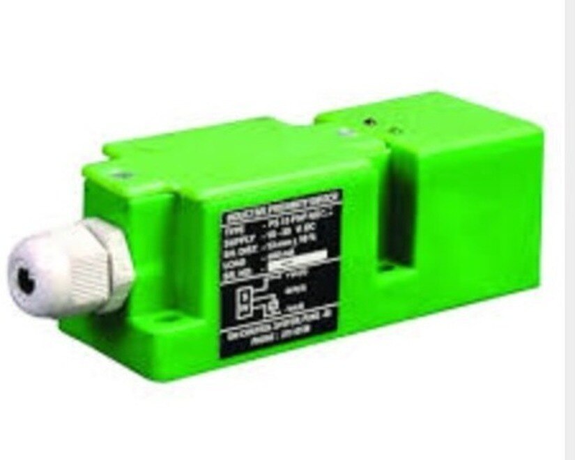
Choosing between a square and cylindrical inductive sensor starts with the bracket, target path, clearance, vibration, and controller—not the housing shape alone. By the end, you will have a practical comparison method covering mounting, sensing performance, wiring, railway evidence, and the questions to put into a Pune purchase specification.
Key takeaways
- Measure access, target travel, cable route, and mounting holes before choosing sensor shape.
- Choose square mounting when fixed alignment matters under vibration and limited access.
- Confirm sensing distance, target steel clearance, connector, voltage, and output type.
- Request railway installation evidence and record every requirement in the purchase specification.
Start with the installation, not the sensor shape
The square inductive sensor versus cylindrical sensor rail equipment in Pune decision starts with the installation envelope, not the housing outline. Measure the existing hole, radial access, sensing-face orientation, target movement, cable route, and space for a connector or locknut.
A flat guard plate or bracket with limited side access favours a square body; a threaded M12, M18, or M30 hole favours a cylindrical barrel.
| Option | Physical advantage | Choose it when |
|---|---|---|
| Square | Flat face, slotted mounting, lateral adjustment | You need orientation-resistant mounting on a plate, greasing machine, trackside bracket, or conveyor-adjacent guard |
| Cylindrical | Threaded barrel, locknuts, compact axial installation | You have a prepared hole, one-sided access, or need a rigid, repeatable replacement |
| Either | Detection depends on coil, target, clearance, and construction | The mounting envelope accepts both forms and the sensing specification matches |
Do not infer sensing distance from shape. Check flush or non-flush construction, target steel grade and dimensions, minimum gap, nearby steelwork, and whether vibration can move the target or loosen the bracket. Secure the connector, cable exit, locknuts, and target; these parts can fail before the electronics.
For onboard rolling stock, also request manufacturer evidence for EN 50155 conditions and evaluate the installed assembly against EN 61373 vibration and shock categories. Depot, wayside, and fixed equipment follow a different assessment path, so a metal housing alone proves nothing.
Choose the mounting form that stays aligned under vibration
Square inductive sensor mounting is better when a flat plate, limited radial access, or a fixed sensing-face orientation matters more than fine axial adjustment. Use a keyed bracket or dowel; an unsecured slotted square body can shift under vibration and change the target gap.
| Mounting form | Mechanical advantage | Main failure risk |
|---|---|---|
| Square body | Broad face, orientation-resistant bracket, lateral adjustment | Slotted bracket shifts unless positively keyed |
| Threaded cylindrical barrel | M12, M18, or M30 hole; locknuts allow axial setting and replacement | Loosening, rotation, or poor thread engagement |
A threaded barrel offers stronger retention when the equipment already has a tapped hole, access is available from one side, or the target gap needs precise axial setting. Tighten locknuts to the manufacturer’s torque, verify thread engagement, and add anti-rotation control; friction alone lets vibration turn the sensing face away from the target.
For a square sensor or cylindrical sensor in Pune, record these installation facts before choosing:
- Mounting envelope, bracket thickness, and wrench access
- Required lateral or axial adjustment
- Vibration, impact, oil, brake dust, and washdown exposure
- Connector orientation and cable bend radius
Neither shape proves railway suitability. Onboard rolling-stock equipment needs different evidence from a depot, conveyor, or wayside assembly, so request test documentation for the actual installation category.
Compare sensing geometry, target approach, and steel clearance
Flush mounting shortens the rated gap but permits steel around the sensing face; non-flush construction can reach farther only when the specified metal-free zone remains clear. Ignore that zone and a rail bracket, guard, or mounting plate can trigger false switching.
| Option | Geometry and approach | Real gap and steel clearance |
|---|---|---|
| Square | Broad face suits a target passing square-on across a fixed plane; slots allow lateral adjustment. | Gap depends on coil size, not the housing outline. Keep the face aligned and key the bracket, or vibration can move the setting. |
| Cylindrical | A recessed M12, M18, or M30 barrel protects the face and suits one-sided threaded installation. | A small barrel can have less range than a large square unit. Locknuts hold position, but angled or edge-on targets reduce repeatable detection. |
| Either form | Flush or non-flush construction determines the surrounding-metal rule. | Catalogue distance uses a standard mild-steel target. Stainless steel, aluminium, a small target, or an irregular profile needs correction-factor or target-specific data. |
The sensing face should meet the target as squarely as the mechanism allows. A target approaching at an angle presents less metal to the coil, reducing the effective gap; a nearby steel guard can do the opposite by becoming the detected target.
This is the practical point in an inductive sensor shape comparison: compare coil diameter, construction, target, and clearance—not square versus cylindrical labels alone.
Measure the steel-free zone around the face at the nearest point in travel, then test the actual target at its coldest, dirtiest, and most misaligned position.
Verify the electrical interface and railway installation evidence
Confirm the electrical interface and railway evidence before wiring either shape to a PLC, relay, train-detection controller, or grease-pump controller.
An M18 thread or square footprint proves nothing about compatibility: PNP or NPN, normally open or normally closed, two-wire or three-wire connection, DC voltage range, residual current, voltage drop, switching frequency, and connector pinout must match.
1. Obtain the controller wiring diagram and sensor datasheet. Check supply-voltage variation, interruption behaviour, output load, polarity, and whether the input interprets NO and NC logic correctly.
2. Confirm the connector orientation, pin assignment, cable length, minimum bend radius, and strain relief. On vibrating rail equipment, a loose locknut, stiff bracket, damaged cable exit, or poorly fixed target can fail before the sensing electronics.
3. Identify the location. Onboard rolling-stock installation requires evidence relevant to EN 50155 and vibration and shock testing under EN 61373 for the installed assembly. Depot, conveyor, or wayside equipment may follow fixed-installation requirements instead.
4. Request the manufacturer’s declaration, test report, or application statement for operating temperature, humidity, electrical transients, vibration, and impact. A metal housing is not railway compliance.
5. Check the complete sensor-and-connector arrangement against IEC 60529 IP testing, oil, brake dust, ultraviolet exposure, corrosion, monsoon water, and pressure washing. IP67 alone does not prove resistance to those conditions.
For a rail equipment proximity sensor in pune, record these documents with the part number; do not accept “railway grade” as evidence without a named standard and test scope.
Turn the comparison into a Pune purchase specification
Record the installation as a specification before requesting prices. A square sensor or cylindrical sensor in Pune is not a complete choice until the supplier can match the site conditions and provide evidence.
1. Measure the mounting envelope: hole diameter, bracket thickness, available sensing-face access, replacement clearance, connector orientation, and minimum cable bend radius. State whether the existing mount requires a threaded M12, M18, or M30 barrel, or a bolted square body.
2. Describe the target precisely: steel grade, target dimensions, approach direction, required gap, and the nearest fixed metalwork. Ask for the manufacturer’s rated distance at that target, including whether the construction is flush or non-flush.
3. Record vibration, shock, and impact exposure, then identify the location as onboard rolling stock, depot equipment, conveyor-side machinery, or wayside equipment. Ask for EN 61373 test evidence for the installed location; a metal housing proves nothing.
4. Specify water, dust, oil, grease, cleaning chemicals, washdown pressure, and required IP rating. Include the operating temperature and humidity range.
5. Confirm supply-voltage variation, interruption behaviour, switching frequency, output type, logic, load current, short-circuit protection, and transient immunity. Do not treat a proximity sensor as a safety device without complete safety-function validation.
6. Request the datasheet, dimensional drawing, wiring diagram, conformity declaration, and applicable EN 50155 evidence for onboard use. SAI CONTROL SYSTEM should identify which documents apply to the exact model, not a similar housing.
Related products
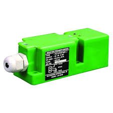 | Inductive Proximity Sensor Square Type Inductive Proximity Sensor The Square Type Inductive Proximity Sensor from Sai Control Systems is a high-performance, non-contact sensor designed for efficient and reliable... View product → |
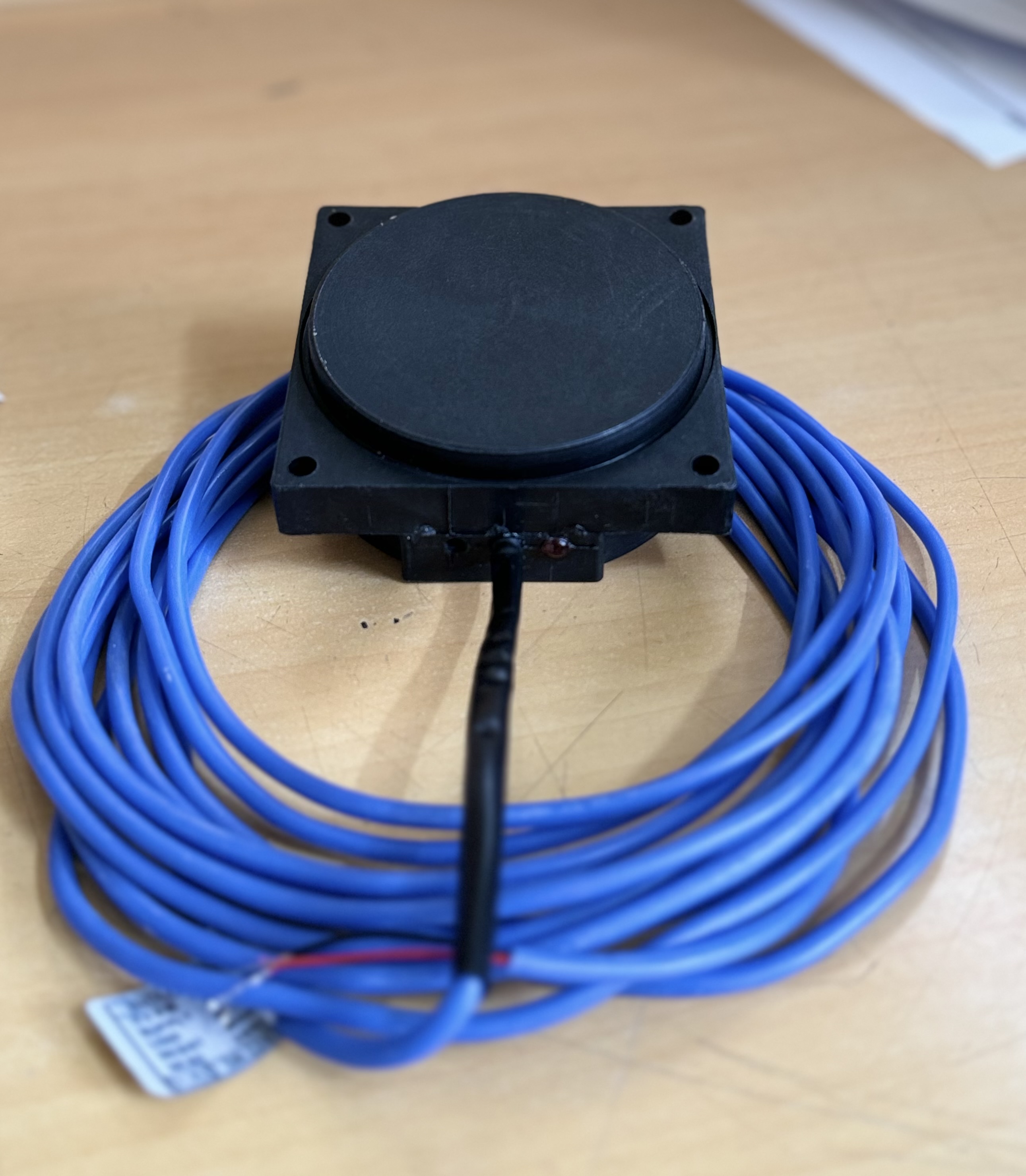 | Inductive Proximity Sensor Automatic Rail Track Grease Lubrication Sensor These sensors are used to detect passing trains, which activates the pump to deliver the correct amount of grease to the wheel flange and rail in... View product → |
Frequently asked questions
Should you choose a square or cylindrical inductive sensor for Pune rail equipment?
Choose the form that fits the existing installation envelope and stays aligned with the moving target under vibration. Measure mounting holes, radial access, sensing-face orientation, cable routing, and connector or locknut space first.
How do square and cylindrical inductive sensors differ in mounting?
Square sensors suit fixed mounting where a defined face orientation and anti-rotation control matter. Cylindrical sensors suit drilled holes, threaded mounting, and installations that need axial adjustment with nuts.
What sensing details must you compare before buying?
Compare target approach direction, sensing distance, steel target size, clearance from surrounding metal, switching frequency, supply voltage, output type, and connector or cable arrangement.
What railway evidence should you request from a sensor supplier?
Request the exact model datasheet, wiring diagram, environmental ratings, test records, installation references, and evidence that the sensor has operated in a comparable railway equipment application.
Related products
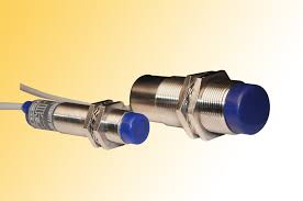 | Inductive Proximity Sensor The Inductive Proximity Sensor from Sai Control Systems is a vital component for modern industrial automation, offering non-contact metal detection... View product → |
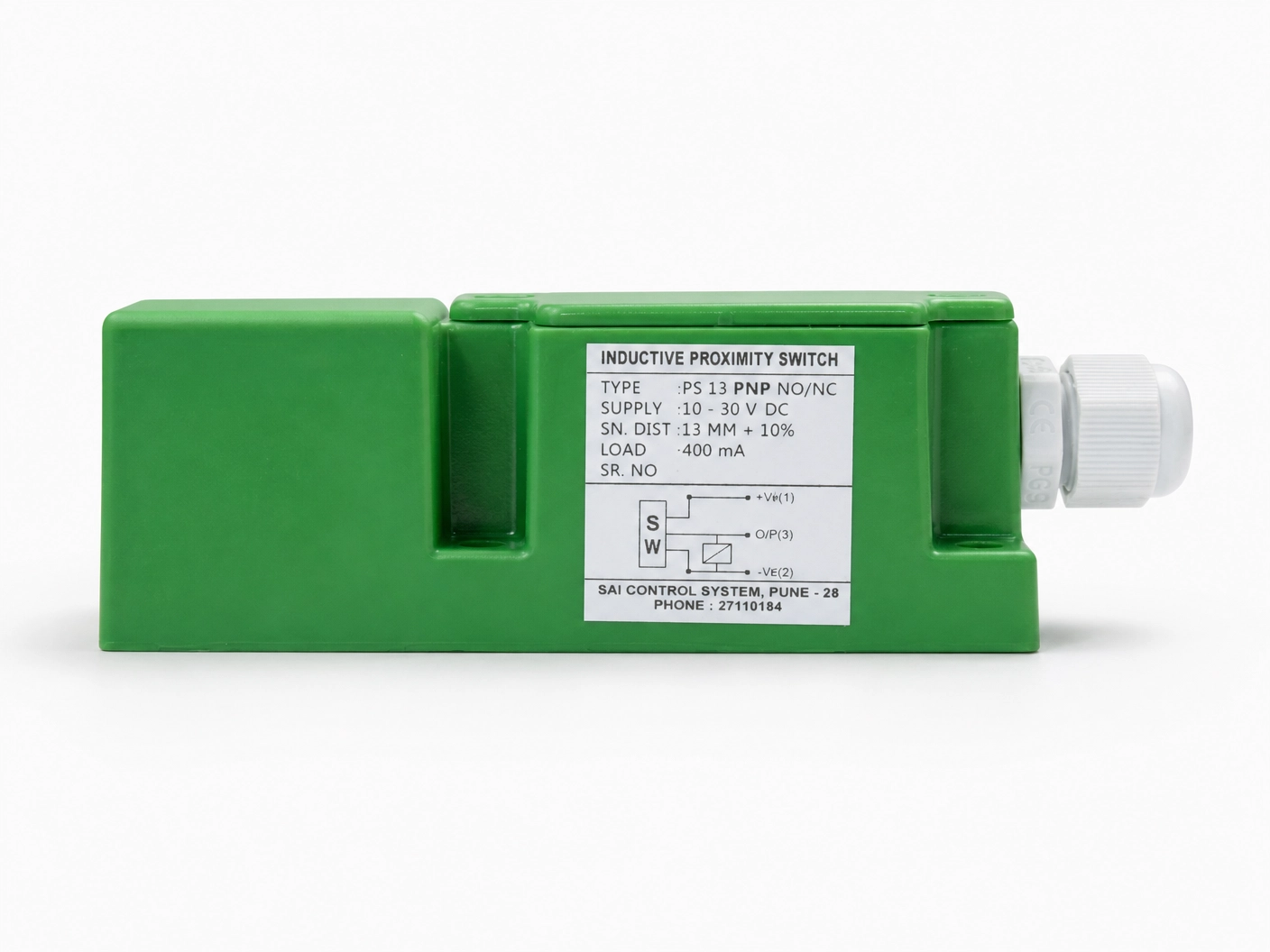 | Inductive Proximity Sensor Model: IPS13PNODF40 Size : 40*40*112mm Logic : PNP NO Sensing Distance : 15mm Sensing Face : Front Connection : PG Gland View product → |