Water on a sensing face is not the same fault as water inside a connector, cable entry, or sensor body. You will learn how to identify the failure mechanism, test the sensor against the PLC input, separate installation faults from electronic failure, and specify protection that matches your plant’s actual washdown conditions.
Key takeaways
- Inspect the connector, cable entry, and potting before blaming the sensing face.
- Match symptoms to faults: intermittent output points to moisture or a loose connection.
- Test supply voltage, switching output, and insulation before replacing the sensor.
- Specify IP67 or IP68 only after checking washdown pressure, chemicals, and immersion risk.
How Moisture Creates Inductive Switch Failures
Water on the sensing face does not normally make an inductive proximity switch detect water as a capacitive sensor would. The serious inductive sensor moisture problems usually begin when water reaches the connector, cable entry, potting, or internal circuit.
Trace the failure through the exposure path:
- Washdown spray enters a damaged seal or loose cable gland, creating leakage between conductors. The output can switch intermittently, remain active, or send a false signal to the PLC.
- Cold water hitting a warm sensor creates internal or connector condensation without visible standing water. Repeated wet-dry cycles corrode contacts and reduce insulation resistance.
- Cleaning chemicals attack seals, cable jackets, connector plating, and potting compounds. IP67 proves temporary immersion protection; it does not certify resistance to chemicals, continuous spray, or thermal shock.
- Conductive or metallic residue bridges terminals and changes the sensor’s electrical behaviour. Residue around a non-flush sensor can also bring nearby metalwork into its sensing field.
- Water, residue, or a loosened bracket can shift the target gap. The switch then misses metal targets even though its electronics remain undamaged.
These proximity switch wet environment issues depend on the exposure zone, not simply the plant’s location. Specify hose pressure and temperature, chemical cleaning agents, immersion duration, connector type, cable length, and temperature limits for both process heat and cold washdown.
Choose flush mounting where mechanical protection matters; choose non-flush mounting only when its longer range and exposed sensing field are controlled.
Match the Symptom to the Electrical Fault
A wet sensing face alone does not make an inductive switch detect water. For inductive sensor moisture problems, separate the symptom from the exposure: internal condensation, conductive residue, connector leakage, corrosion, or a shifted mounting position produces the electrical fault.
| Symptom | Likely fault | Distinguishing clue |
|---|---|---|
| False ON signal | Leakage between conductors, wet connector, or conductive residue | The output stays active with no metal target; drying the connector or fitting a dry spare removes the signal. |
| Missed metal target | Excessive target gap, displaced bracket, reduced supply voltage, or damaged sensing coil | The switch responds when the target is moved closer, but not at its normal position. |
| Unstable switching | Condensation, loose M12 coupling nut, damaged O-ring, cable strain, or corroded pins | The signal changes when the cable or connector is moved, or during temperature changes. |
| Permanently active PNP output | Black output wire shorted to brown positive supply, or failed output transistor | The PLC input remains ON with the target absent and the output wire isolated. |
| PLC alarm | Low supply, excessive voltage drop under load, input incompatibility, or intermittent common connection | Measure brown-to-blue voltage at the sensor and compare it with the PLC input state. |
| Connector corrosion | Water entry, chemical attack, or dissimilar-metal crevice corrosion | Green, white, or pitted contacts appear even when the sensor face is intact. |
| Washdown-only fault | Spray-driven ingress, cold-water condensation, or seal contraction | The failure occurs during hose-down and clears after drying. |
For process plant sensor failures in Pune, record whether the fault follows washdown, monsoon humidity, or a chemical-cleaning cycle. That timing separates a damaged switch from an installation that only fails when wet.
Test the Sensor Before Replacing It
A 24 VDC reading at the sensor does not prove the sensor works; it proves only that supply voltage reaches it. For proximity switch wet environment issues, test under operating conditions, then separate the sensor from the cable and PLC input.
- Measure brown-to-blue at the sensor: confirm the manufacturer’s rated voltage during switching, not only at rest. Measure again with the output loaded; a sharp drop indicates a weak supply, wet connector, or high-resistance cable.
- Back-probe black-to-blue. A PNP output should approach 0 V when OFF and supply voltage when a steel target enters the specified gap. No change points to the sensor, target distance, or cable.
- Power off and check cable continuity end-to-end, conductor-to-conductor shorts, and each conductor to shield or plant earth. Low insulation resistance identifies moisture or chemical damage.
- At the PLC terminal, check the input LED and diagnostic bit while moving the target. Substitute a dry, known-good sensor on the same cable and input; a normal result shifts suspicion to the removed sensor or connector.
| Finding | What it proves | Fault to pursue |
|---|---|---|
| Supply low under load | Voltage collapses at operation | Power supply, connector, or cable |
| Sensor output correct; PLC stays ON | Signal reaches the interface incorrectly | Leakage current, wet cable, or incompatible input |
| Output absent at sensor | Sensor never switches | Target gap, sensor, or supply |
| Sensor works on a spare cable | Original path is defective | Connector or cable |
| Washdown-only failure | Moisture triggers the fault | Seal, connector, or insulation; a common clue in process plant sensor failures in Pune |
Specify Protection for the Actual Wet Area
IP rating is only a water-ingress comparison; it does not certify chemical resistance, thermal-shock survival, or a separate connector. Specify inductive proximity switch protection for wet areas against the actual washdown method.
| Rating | Water exposure covered | Use it when | Important limitation |
|---|---|---|---|
| IP65 | Dust-tight and water jets | The area receives low-pressure spray or splashing | It is not an immersion rating and does not cover powerful washdown jets |
| IP66 | Dust-tight and powerful water jets | Hose-down cleaning reaches the sensor directly | It does not prove survival under immersion or chemical attack |
| IP67 | Dust-tight and temporary immersion | A sensor can fall into a tank or remain submerged briefly | It is not automatically suitable for continuous spray or pressure washing |
| IP69K / ISO 20653 | Defined high-pressure, high-temperature spray test | Hot, directed washdown is part of the cleaning cycle | It does not validate your chemicals, cable, connector, or repeated thermal shock |
Record the washdown pressure and temperature, process temperature, immersion duration, cleaner concentration, contact time, rinse method, and solvent, acid, caustic, or chlorine exposure. A cold rinse can contract seals after a hot process cycle and create leakage even when the ambient-temperature rating looks adequate.
Treat the connector as a separate decision. Select a factory-sealed connector or gland, route the cable downward with a drip loop, add strain relief, and shield the sensing face from direct spray. Installer-applied silicone is not a substitute for tested sealing.
For the search phrase “inductive proximity switch for problems in wet process plants in pune,” SAI CONTROL SYSTEM can help compare the sensor, gland, cable length, target material, and diagnostic behaviour against the zone specification—not IP marking alone.
Related products
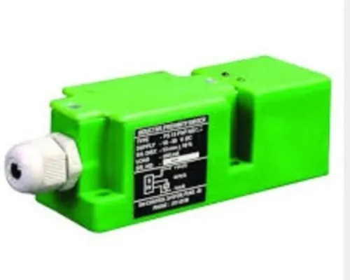
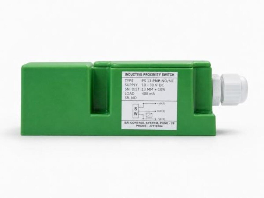
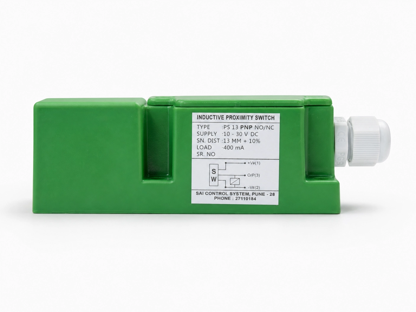 | Inductive Proximity Sensor Model: IPS13PNODF40 Size : 40*40*112mm Logic : PNP NO Sensing Distance : 15mm Sensing Face : Front Connection : PG Gland View product → |
 | Inductive Proximity Sensor The Inductive Proximity Sensor from Sai Control Systems is a vital component for modern industrial automation, offering non-contact metal detection... View product → |
Install and Maintain the Switch for Washdown Survival
An IP67 inductive proximity switch can still fail in a hose-down zone: IP67 covers temporary immersion, not continuous spray, cleaning chemicals, or repeated thermal shock. Effective inductive switch protection for wet areas combines the sensor rating with the connector, cable route, mounting, and washdown method.
Build the installation around these controls:
- Use a sealed connector that matches the sensor, tighten it to the manufacturer’s torque, and keep the joint out of the spray path.
- Route the cable downward from the connector or form a drip loop so water cannot run into the cable entry.
- Add strain relief and leave enough cable for inspection without pulling on the connector.
- Shield the sensor from direct spray with a bracket or guard that does not enter its sensing zone.
- Select corrosion-compatible stainless mounting hardware and prevent brackets from flexing under vibration.
- Choose flush mounting where nearby metal or residue could affect a non-flush sensor’s exposed sensing field.
- Specify operating limits for process heat and cold-water washdown, not ambient temperature alone.
During cleaning, follow the approved pressure, temperature, nozzle distance, and chemical concentration. Do not aim a high-pressure jet at the connector or cable gland, and allow hot equipment to cool within the sensor’s rated washdown range before cold water hits it.
Inspect seals, cable jackets, connectors, and mounting alignment after each planned maintenance interval. Do not add field-applied silicone or potting: it can hide a failed seal and obstruct the sensing face. These controls address proximity switch wet environment issues at their entry points.
Frequently asked questions
How does moisture create inductive proximity switch failures?
Moisture causes failures when it reaches the connector, cable entry, potting, or internal circuit. Water on the sensing face does not normally make an inductive sensor detect water.
How can you match a sensor symptom to an electrical fault?
An intermittent output points you toward moisture ingress, cable damage, a loose connector, or unstable supply voltage. A constant output requires checks for a short circuit, incorrect wiring, or a failed switching stage.
What should you test before replacing an inductive proximity switch?
Check supply voltage at the sensor, confirm the wiring and connector condition, measure the switching output with a target present and absent, and inspect insulation or continuity where moisture is suspected.
How do you specify inductive switch protection for wet areas?
Assess washdown pressure, water temperature, cleaning chemicals, spray direction, cable-entry exposure, and immersion risk. Then select a suitable enclosure rating, connector, cable, and mounting arrangement rather than relying on an IP rating alone.
Related products
 | Proximity Switches The Omron Proximity Switch is a robust and dependable sensing device designed to deliver accurate object detection across a wide range of industrial... View product → |
 | Inductive Proximity Sensor Automatic Rail Track Grease Lubrication Sensor These sensors are used to detect passing trains, which activates the pump to deliver the correct amount of grease to the wheel flange and rail in... View product → |