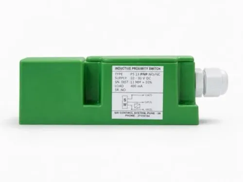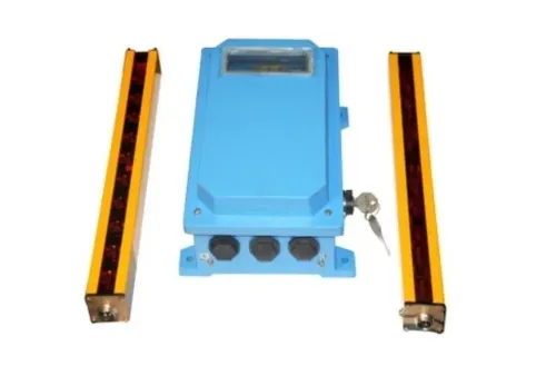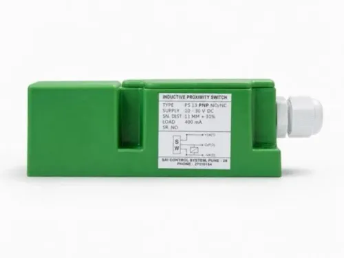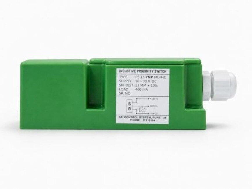
The right choice depends first on what must be detected: conductive metal, or a magnetic actuator that can sit on plastic or aluminium. Compare the operating principle, target geometry, electrical interface, speed, contact limits and installation conditions before you commit to a sensor or specify an inductive proximity switch manufacturer.
Key takeaways
- Choose inductive sensors for direct detection of conductive metal targets.
- Choose magnetic reed switches for magnet-equipped doors, cylinders and position sensing.
- Check NPN or PNP logic, normally open or closed state, and PLC input voltage.
- Compare sensing distance, switching frequency, repeatability and contact-current limits.
How the two sensors create a switching signal
An inductive proximity sensor uses an oscillator to create an electromagnetic field at its sensing face. When a conductive target enters that field, the target changes the oscillator condition; an electronic switching circuit detects the change and changes state.
A magnetic reed proximity switch uses a different mechanism: a permanent magnet moves ferromagnetic reeds inside a sealed glass tube until the contacts close or separate.
| Device | Position detection | Normal switching output |
|---|---|---|
| Inductive proximity sensor | Conductive target changes an electromagnetic field | Semiconductor PNP or NPN transistor output |
| Magnetic reed proximity switch | Permanent magnet moves sealed ferromagnetic reed contacts | Galvanically isolated dry contact |
Normally open, or NO, means the output is non-conducting in the resting state and changes to conducting or ON when the target arrives. Normally closed, or NC, conducts while the sensor is at rest and opens when actuated.
For an inductive sensor, NO or NC describes the transistor output logic, while PNP or NPN describes how that transistor switches the circuit.
A PNP output sources current toward the positive supply; an NPN output sinks current toward 0 V. Reed contact logic depends on the actuator’s magnet and the contact arrangement, not on PNP/NPN terminology. A reed switch therefore behaves like an isolated switch contact, not like a three-wire transistor sensor.
Which targets each sensor can detect, and how far away
Choose an inductive proximity sensor for conductive metal targets; choose a magnetic reed proximity switch when a magnet can be fitted to the moving part. The inductive device detects aluminium, brass, copper and stainless steel, but its rated distance normally uses a standardized mild-steel target under IEC 60947-5-2 test conditions.
| Sensor | Detectable target | Distance and limitation |
|---|---|---|
| Inductive proximity sensor | Conductive metal | Non-ferrous metals often give a shorter usable distance because they couple differently to the electromagnetic field. Target size, thickness, shape, approach direction and sensor-face orientation also change the result. |
| Magnetic reed proximity switch | A suitable permanent magnet, including one mounted on plastic, aluminium or another nonmagnetic carrier | Magnet polarity, alignment, approach direction, nearby steel and neighbouring magnets shift operate and release points. |
Ordinary plastic, glass, wood and dry product do not normally trigger an inductive field. For details, test the complete target at its final gap rather than treating the nameplate distance as universal.
Flush inductive mounting places the sensing face level with surrounding metal; non-flush mounting projects the face and needs the manufacturer’s specified clearance around it. Leave the specified separation between adjacent inductive sensors, or their fields can interact and cause false switching.
A reed switch instead needs its magnet aligned through the correct face and polarity, with nearby steel and other magnets kept clear; validate both operate and release points in the installed geometry.
How output logic and wiring affect a PLC input
For a 10–30 V DC three-wire sensor, confirm the product datasheet before using this convention:
- Connect brown to the positive supply.
- Connect blue to 0 V.
- Connect black to the PLC input as the switched output.
An inductive proximity sensor may be PNP or NPN, so match its output type to the PLC input circuit. PNP sourcing drives the input toward positive voltage; NPN sinking pulls the input toward 0 V.
| Device | Output | PLC connection |
|---|---|---|
| Inductive proximity sensor | PNP or NPN transistor | Match the PLC input circuit and output polarity |
| Magnetic reed proximity switch | Two-wire galvanically isolated dry contact | Place the contact in series with the input or load |
Check minimum ON current, OFF leakage current, voltage drop, reverse-polarity protection and short-circuit behaviour. A three-wire transistor sensor does not automatically replace a two-wire reed contact.
Normally open (NO) and normally closed (NC) choices change both fail-state interpretation and PLC logic. An NO device conducts when actuated; an NC device conducts at rest and opens when actuated.
Protect the circuit with the specified fuse and correct polarity. If the sensor cannot drive the load directly, use an interface relay or suitable input module. Check the relay coil or module input rating rather than assuming the PLC input will accept every sensor output.
Speed, repeatability and the real electrical limits
For a high-cycle conveyor, an inductive proximity sensor usually switches more cleanly: its oscillator and semiconductor output respond without moving contacts. Its switching frequency still depends on output response, target size, target spacing and the time needed for the field to recover.
| Sensor | Speed and repeatability limits | Failure concern |
|---|---|---|
| Inductive proximity sensor | High switching frequency when the target is large enough, correctly spaced and within the specified gap | A small target or insufficient spacing can reduce frequency and cause missed pulses |
| Magnetic reed proximity switch | Limited by mechanical operate and release time, contact bounce and the specified cycle rate | One magnet pass can create several PLC transitions instead of one |
Inductive hysteresis separates the operate and release distances, reducing chatter. If vibration holds a target between those thresholds, the output can still change position unpredictably, so conveyor stop repeatability must include hysteresis, target speed and vibration.
A magnetic reed proximity switch also needs a shock, vibration and glass-envelope stress check. Contact bounce calls for PLC debounce, an input filter or interface electronics when one pass produces false counts or multiple transitions.
Check reed contact voltage, steady current and switching capacity together. Lamps, solenoids and capacitive PLC inputs create inrush; add a DC flyback diode or an AC RC snubber or varistor where specified. Use a relay or interface when the load or its inrush exceeds the reed rating.
For high-cycle service, an inductive sensor’s lack of moving contacts is usually safer.
A specification checklist for choosing the right supplier and sensor
Before comparing an inductive proximity switch manufacturer, put the complete application in the purchase specification. Use the phrase inductive proximity sensor magnetic reed proximity switch for details only as a starting search, not as a substitute for these fields:
- Target material and dimensions; required gap; approach direction; flush or non-flush mounting; hysteresis; switching frequency.
- NO or NC logic; PNP or NPN output; two-wire or three-wire wiring; supply-voltage range; PLC input requirements.
- Ingress protection, connector or cable gland, temperature range, cable-flexing conditions, EMC environment and required approvals.
| Choice | Specify | Why it matters |
|---|---|---|
| Inductive | Conductive target, face clearance and sensor separation | Steel, aluminium, target size and nearby oscillators change the usable gap |
| Reed | Magnet size, polarity, alignment and surrounding steel | Magnetic interference shifts operate and release points |
Validate the complete assembly at its final mounting geometry. Test reed magnets beside the actual steelwork and adjacent magnets, and test adjacent inductive sensors at their installed spacing.
Hazardous-area and safety-related use require separate confirmation. “Inductive” and “reed” do not establish certification or safety suitability; verify the complete sensor, connector, wiring method and interface.
SAI CONTROL SYSTEM can add value by comparing the interface with your PLC, checking conveyor or feeder constraints, and confirming target and environmental details before supply. Choose the supplier that documents electrical and mechanical fit, not merely nominal sensing distance.
Related products
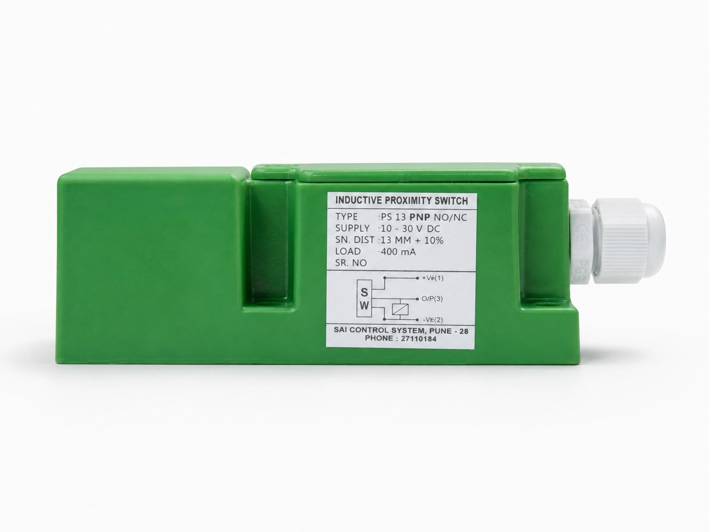 | Inductive Proximity Sensor Model: IPS13PNODF40 Size : 40*40*112mm Logic : PNP NO Sensing Distance : 15mm Sensing Face : Front Connection : PG Gland View product → |
 | Inductive Proximity Sensor The Inductive Proximity Sensor from Sai Control Systems is a vital component for modern industrial automation, offering non-contact metal detection... View product → |
Frequently asked questions
How do inductive and magnetic reed proximity switches create a switching signal?
An inductive proximity sensor detects a change in its electromagnetic oscillator field when a conductive target enters the sensing zone. A magnetic reed proximity switch uses a magnetic field to move contacts inside a sealed reed capsule and open or close the circuit.
Which targets can each sensor detect, and how far away?
Inductive sensors detect conductive metals, with sensing distance affected by target material, size and orientation. Magnetic reed switches detect a magnet or a magnet-equipped actuator, and their operating distance depends on magnet strength, alignment and switch design.
How do output logic and wiring affect a PLC input?
Match the sensor’s supply voltage, output type and switching state to the PLC input. Check whether the inductive sensor is PNP or NPN and normally open or normally closed; a reed switch requires wiring that suits the input circuit and its current rating.
What speed, repeatability and electrical limits should you compare?
Compare switching frequency, response time, repeatability and hysteresis for motion. Also verify load current, voltage, leakage current, voltage drop, contact bounce and inductive-load protection before connecting either device to a PLC.
Related product
 | Inductive Proximity Sensor Square Type Inductive Proximity Sensor The Square Type Inductive Proximity Sensor from Sai Control Systems is a high-performance, non-contact sensor designed for efficient and reliable... View product → |