An inductive sensor does not detect a jammed mass of grain, coal, powder, plastic, or wood; it detects a conductive target in its sensing field. You will be able to judge when a metal paddle-and-target mechanism is dependable, how to prevent false trips, and what electrical and mechanical details to require before purchase.
Key takeaways
- Use a metal target because an inductive sensor detects metal, not material flow.
- Mount a rigid, repeatable target where the chute blockage moves it into sensing range.
- Separate vibration, buildup and genuine jams with stable mounting and timed logic.
- Specify sensing distance, target size, IP rating and fail-safe shutdown behavior.
What an inductive sensor actually detects in a chute
An inductive proximity sensor cannot identify a blocked chute on its own. It detects conductive metal inside its electromagnetic sensing field, not the bulk material or the absence of flow.
If the chute carries grain, powder, plastic, wood, rubber, or coal, the buildup will not trigger the sensor directly. Use a pivoting flap, paddle, striker, or retaining plate that moves a metal target into the sensing zone when material accumulates.
| Option | What it detects | Main limitation |
|---|---|---|
| Inductive sensor alone | A nearby conductive metal target | Cannot confirm that product has stopped flowing |
| Inductive sensor with flap or paddle | The metal target’s jam position | Depends on a free-moving mechanism and correct target alignment |
| Complete mechanical chute jam switch | Paddle displacement caused by conductive or nonconductive buildup | Requires exposed moving parts that can bend, seize, or collect material |
A mechanical chute jam switch responds to paddle movement, so the buildup itself can be conductive or nonconductive. An inductive arrangement instead detects the mechanism’s position and needs a separate metal target attached to it.
The arrangement can detect a jam reliably when the chute mechanism converts accumulation into a repeatable target position. Set a defined trip point, provide enough movement beyond that point for a stable signal, and ensure the paddle returns cleanly after the blockage clears.
The sensor alone cannot confirm flow stoppage. A bent paddle, seized pivot, loose bracket, or material-packed mechanism can leave the target outside the sensing zone while the chute remains blocked. Test the actual mechanism during commissioning, not only the sensor input.
How to build a repeatable metal-target arrangement
Give the flap a defined trip position, not a guessed distance. Mount a pivoting or sliding metal flap or target plate to a rigid bracket, then position the inductive sensor so the plate enters its sensing zone when a jam pushes or retains the flap.
Use independent mechanical stops to set the normal and jam positions; do not let the sensor face or bracket serve as a stop. Provide an operating gap that places the target clearly inside the switching zone, with enough overtravel for product surges and vibration.
A printed 15 mm nominal sensing figure is not automatically the usable installation distance. Target size, steel grade, target geometry, nonferrous material, and mounting conditions change the rated operating distance. Request that distance and the manufacturer’s correction factors for your target, then leave installation margin.
Keep fixed chute walls, liners, wear plates, bolts, brackets, and nearby structural steel outside the active sensing area, or they can create a false chute jam switch signal.
Mounting choice changes the clearance required around the sensing face:
| Mounting | Installation effect | Main risk |
|---|---|---|
| Flush | Sensor sits level with surrounding metal and follows the specified flush clearance | A nearby bracket can shorten range or cause intermittent switching |
| Non-flush | Sensor projects beyond metal and needs the stated free zone around its face | Unplanned metal beside the face can cause permanent switching |
A metal bracket placed too close can hold the output on continuously or make it chatter as the flap moves. Verify the actual flap, plate, bracket, and chute assembly at both stops before commissioning.
How to stop vibration and buildup from looking like a jam
Treat a trip as a jam only after testing the mechanism through normal product surges and empty-chute movement. Chute-wall flexing, bracket vibration, dust, moisture, metal fines, wet conductive product, or material stuck to the sensor face can imitate a blockage or prevent reset.
- Run the paddle through its full travel with the chute empty and loaded.
- Check that vibration cannot hold the metal flag near the switching threshold.
- Confirm the target has enough overtravel beyond the trip point for a stable signal and clean reset.
- Check switching frequency and response time if the target oscillates or crosses the sensing field briefly.
Target chatter produces repeated trip-and-reset events instead of one dependable jam signal. Use a mechanically damped paddle and sensor hysteresis to reduce it, then set a PLC delay or timer from the chute’s fill rate and the time available to stop upstream feeding.
Do not filter excessively: a long delay can let a plugged chute keep receiving material. An industrial proximity sensor supplier in Pune should help verify the actual timing against the sensor’s switching specification, not just quote nominal response time.
| Cause | Typical symptom | Correction |
|---|---|---|
| Vibration at threshold | Rapid trip/reset chatter | Add damping, hysteresis, and limited PLC delay |
| Target stops short | No trip or unstable trip | Add defined gap, stops, and overtravel |
| Face contamination | False trip or failed reset | Clean the face and test the worst buildup condition |
How the jam signal should shut down upstream equipment
A jam must remove the run permissive, not create a “clear” signal. Wire the chute jam switch so normal conditions energize a relay or PLC run-permissive input; a jam, broken conductor, sensor removal, or control-power loss then de-energizes it and stops upstream feeding.
| Signalling choice | Behaviour | Main risk |
|---|---|---|
| Normally open | Output closes when the target enters the sensing zone | A broken wire or lost sensor can look like a clear chute |
| Normally closed | Output remains closed in the normal state and opens on a trip | Confirm the sensor and input support this arrangement |
| De-energize-to-run | Relay or permissive stays energized only while conditions are healthy | A control-power loss removes permission to run |
Do not connect an output by label alone. PNP sensors source positive voltage and need a PLC input wired for sourcing devices; NPN sensors switch toward 0 V and need a sinking-input arrangement. Check supply polarity, output current, voltage drop, maximum load, and PLC input thresholds.
Two-wire sensors can leave residual current or voltage when “off,” preventing a PLC input or relay from releasing. Match the sensor to the PLC input or use a correctly rated interposing relay before ordering. A risk assessment must decide whether this circuit is safety-related.
Commission the actual assembly, not a PLC jumper:
- Move the paddle through its real trip position.
- Verify feeder and conveyor shutdown.
- Check cable breaks, sensor removal, and mechanism faults.
- Confirm the intended manual or controlled reset, including after control-power restoration.
What to specify when comparing sensors and chute jam packages
A quotation is comparable only when it describes the same physical solution, not merely a device labelled “chute jam switch.” State whether you need a complete mechanical chute jam switch, only an inductive proximity sensor, or a sensor-plus-target kit.
Ask every supplier to document:
- Output circuit: two-wire, PNP, or NPN; supply polarity, voltage drop, residual off-state current, maximum load, and PLC or relay compatibility.
- Rated operating distance, target material and size assumptions, correction factors for nonferrous metals, and the required flush or non-flush mounting method.
- Temperature range, switching frequency, response time, cable length and type, connector standard, and replacement availability.
- IP rating under IEC 60529 and the applicable product standard, such as IEC 60947-5-2 for proximity sensors.
- Hazardous-area certification and installation requirements where combustible dust or explosive atmospheres exist.
IEC 60529 ingress testing does not prove resistance to abrasive dust, chemical washdown, impact, or explosive atmospheres. A higher IP number cannot replace the correct enclosure, material selection, mechanical protection, or hazardous-area certificate.
When comparing an inductive proximity sensor supplier in Pune, a chute jam switch supplier in Pune, or an industrial proximity sensor supplier in Pune, SAI CONTROL SYSTEM belongs in the same technical comparison only after these points are documented. Location and the label “chute jam switch” do not establish suitability.
Related products
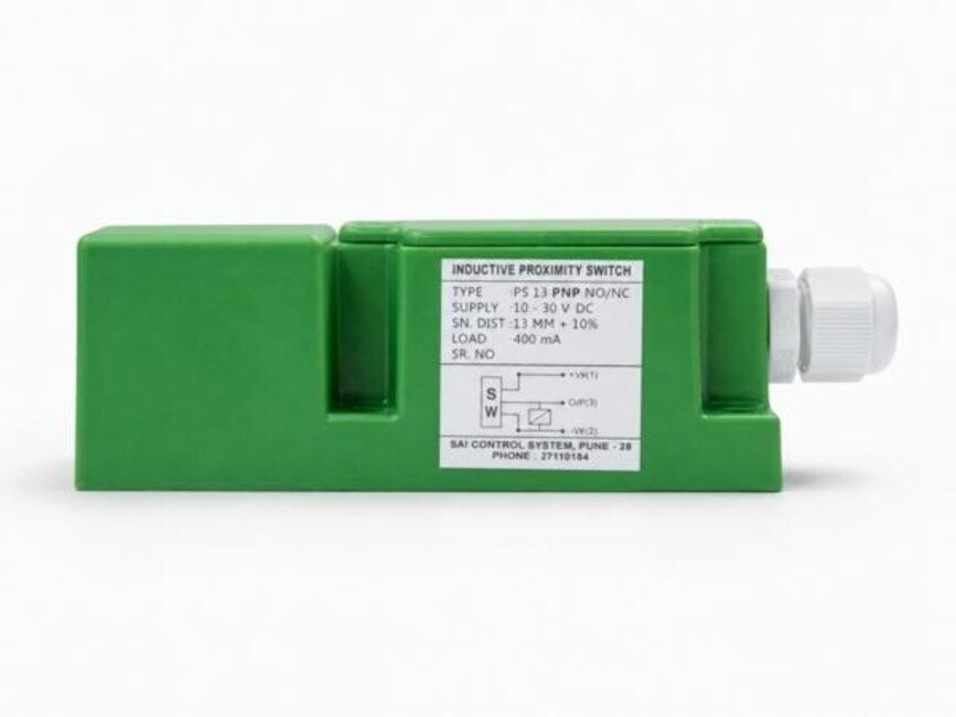
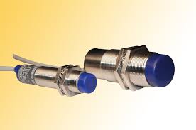 | Inductive Proximity Sensor The Inductive Proximity Sensor from Sai Control Systems is a vital component for modern industrial automation, offering non-contact metal detection... View product → |
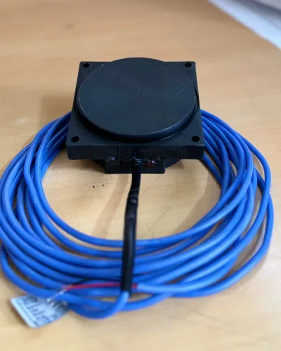
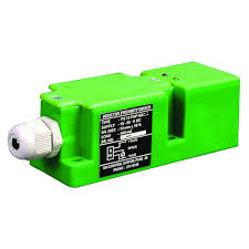 | Inductive Proximity Sensor Square Type Inductive Proximity Sensor The Square Type Inductive Proximity Sensor from Sai Control Systems is a high-performance, non-contact sensor designed for efficient and reliable... View product → |
Frequently asked questions
What does an inductive proximity sensor detect in a chute?
It detects conductive metal entering its electromagnetic sensing field. It does not directly detect bulk material, empty space or lost flow.
How do you build a repeatable metal-target arrangement?
Attach a rigid metal flag, paddle or target plate to the chute’s blockage-detection mechanism and position it at a defined sensing distance.
How do you stop vibration and buildup from looking like a jam?
Use rigid brackets, shield the sensing face from falling material, set a suitable sensing gap and add a time delay before declaring a jam.
How should a jam signal shut down upstream equipment?
Send the sensor signal to a control relay or PLC that stops the feeder and upstream conveyor, latches the fault and requires a manual reset after inspection.
What should you compare when specifying a chute jam switch?
Compare sensing distance, target dimensions, mounting thread, supply voltage, output type, IP rating, response time, temperature range and fail-safe behavior.
Related product
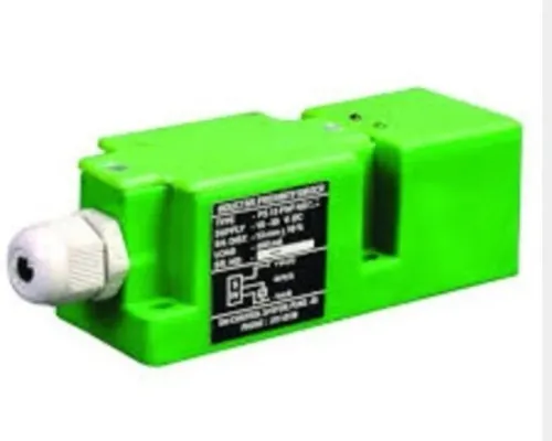
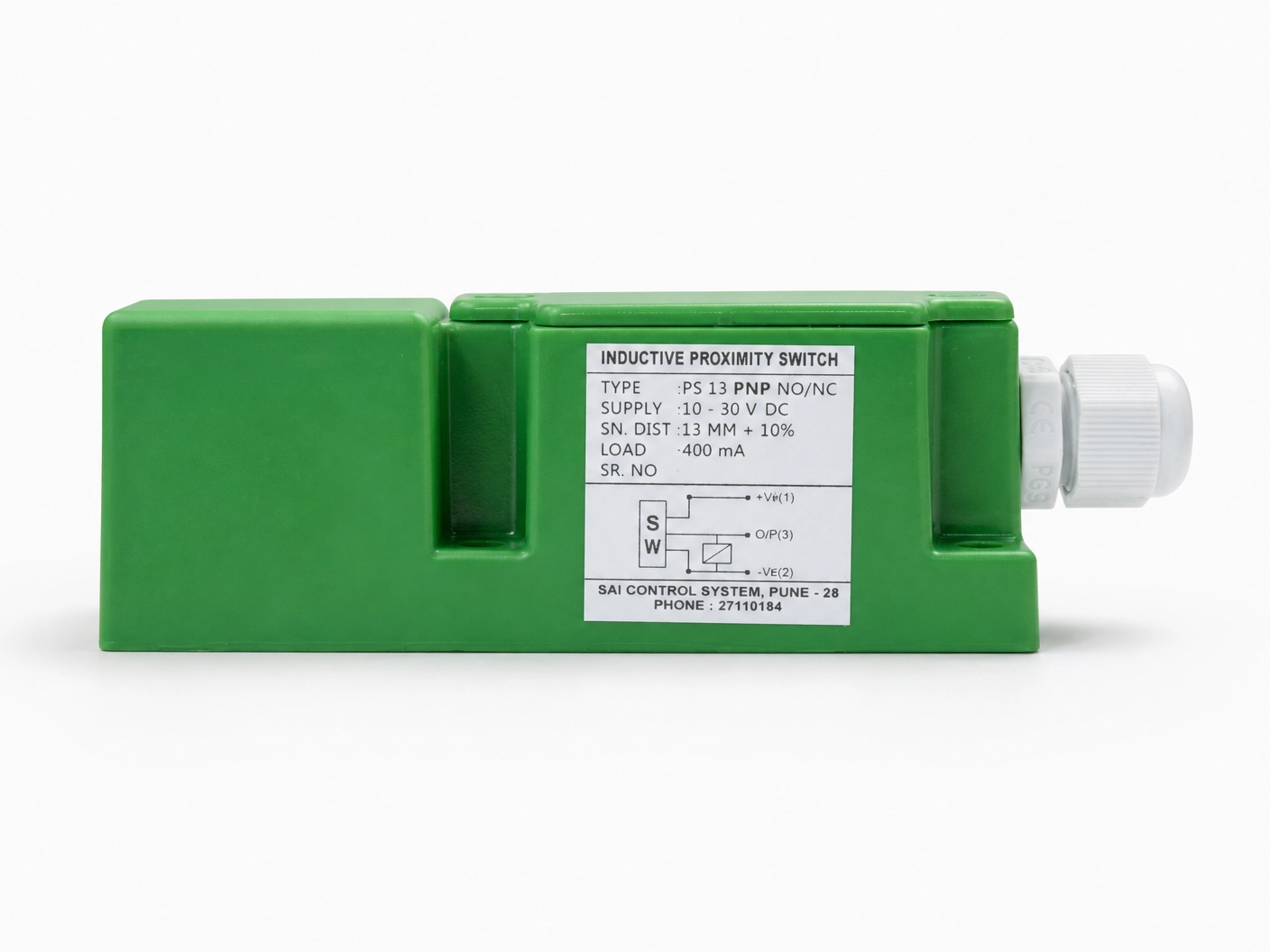 | Inductive Proximity Sensor Model: IPS13PNODF40 Size : 40*40*112mm Logic : PNP NO Sensing Distance : 15mm Sensing Face : Front Connection : PG Gland View product → |