Choosing a sensor by nominal range alone can produce false counts, missed products, or a PLC input that never receives a valid signal. You will be able to match the optical arrangement, electrical interface, environmental protection, and installation method to your actual line conditions before requesting a quotation.
Key takeaways
- Choose through-beam sensing when you can mount emitter and receiver opposite each other.
- Use diffuse, retro-reflective or background-suppression sensing based on target surface and spacing.
- Confirm PLC voltage, PNP or NPN logic, output mode and required counting speed.
- Request sensing range, IP rating, response time and mounting details in every quotation.
How the emitter, receiver and target determine the sensing arrangement
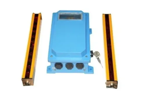
Choose through-beam sensing when you can mount an emitter on one side of the conveyor and a receiver directly opposite it. The target breaks the beam, producing a reliable signal even when its colour or surface finish changes.
| Option | Optical arrangement | Best physical fit | Main risk |
|---|---|---|---|
| Through-beam | Separate emitter and receiver | Open access across the conveyor; long, stable sensing path | Requires two mounting points and precise alignment |
| Retroreflective | Sensor and reflector face each other | Limited wiring and straightforward conveyor installation | Shiny products can reflect light and cause false detection; use polarized models |
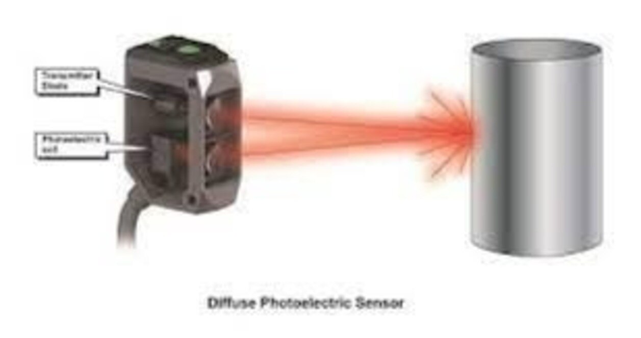
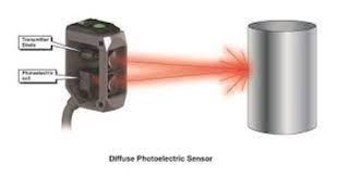
| Diffuse-reflective | Sensor emits and receives target reflection | Short-range detection where one-sided access matters | Dark, angled, or changing surfaces reduce reliability |
| Background-suppression | Sensor measures distance to the target | Products passing close to a fixed frame or wall | Incorrect setup can miss targets outside the taught distance |
| Fiber-optic | Remote sensing head connected by fiber | Tight spaces, heat, vibration, or small-part detection | Fiber bend radius, alignment, and contamination need protection |
The emitter sends light toward the receiver or target; the receiver converts interruption or reflected light into an output. Transparent bottles, film, glass, and clear trays need a sensor designed for transparent-object detection, not a general diffuse model. Fork or slot arrangements suit small parts passing through a fixed gap.
For photoelectric sensor options for production lines in Mumbai, specify the guaranteed operating range, target size, minimum gap, mounting access, and contamination exposure. A nominal range alone does not prove that the arrangement will work.
Match the sensor to cartons, bottles, film and difficult targets
Choose by the target’s optical behaviour, not by nominal sensing distance. Opaque cartons suit through-beam or retro-reflective sensing; diffuse sensing is simpler but can switch at different distances for white cardboard and black rubber. Shiny surfaces and angled bottles can redirect the beam instead of returning it.
| Sensor type | Best match | Main caution |
|---|---|---|
| Through-beam | Opaque cartons, bottles and widely spaced products | Requires an emitter and receiver on opposite sides |
| Retro-reflective | Cartons or bottles where both units cannot be mounted separately | Clear products can pass unnoticed without transparent-object detection |
| Transparent-object | Glass, clear bottles, film and clear trays | Specify optical arrangement and guaranteed minimum object size |
| Background-suppression | Mixed colours or products with a fixed conveyor frame behind them | Confirm the target range and background distance |
| Fiber-optic or fork | Small parts, narrow gaps and crowded conveyor sections | Check fibre bending, alignment and the smallest detectable object |
For bottles, film and glass, do not order a general-purpose diffuse sensor. Ask for transparent-object detection and test the actual wall thickness, curvature, label and gap between products; a clear film edge can be too small or too reflective for the wrong model.
A photoelectric sensor for factory automation also needs a defined target: length, width, height, colour, surface finish and minimum gap. Give the supplier the guaranteed operating range, response time, 10–30 V DC supply requirement, PNP or NPN output, connector or cable, IP rating, temperature range and mounting space.
A laser or colour sensor is worth comparing when dark, glossy or closely spaced products defeat ordinary diffuse sensing.
Check PLC voltage, output logic and counting speed before ordering
A 24 V DC PLC input does not make every 24 V sensor compatible. Check the sensor’s permitted supply range, output rating and wiring diagram; never connect a 220–440 V AC control point to a sensor designed for a 10–30 V DC circuit.
1. Confirm the PLC input voltage and polarity. A nominal 24 V DC system may accept only a narrower range, such as 20–28 V DC. Provide a separate regulated supply or interface module when the available voltage falls outside the sensor’s limits.
2. Match the output type to the input card. A PNP sensor sources positive voltage into the PLC input; an NPN sensor pulls the input down to 0 V. A PNP-only card will not read an NPN output without an interface, and reversing the wires can damage equipment.
3. Specify light-on or dark-on operation. Light-on energises the output when the receiver sees light; dark-on energises it when the beam is blocked. Choosing the wrong logic reverses the count or leaves a safety interlock in the wrong state.
4. Compare response time and switching frequency with product spacing. A fast photoelectric sensor for factory automation still loses counts if the PLC input filter is longer than the target pulse. Check sensor response, PLC filter time, conveyor speed and the minimum gap together.
Confirm the sensor output can supply the PLC input current, then test several production cycles at maximum speed. Order the exact connector, cable length, PNP or NPN version and logic option; a model family name alone does not establish compatibility.
Adapt installation to dust, humidity, sunlight and machine vibration
Mount the optical axis away from direct sunlight, steam outlets and dust discharge points. Sunlight entering a receiver can mimic the emitter, while airborne dust on the optical window weakens the beam until a good target appears absent. Add a short, opaque sunshade without blocking the sensing path.
Use a protective lens shield where cartons, powder or oil can strike the sensor, and leave enough clearance to clean the window without removing the unit.
Choose the ingress rating for the actual exposure: IP67 helps against temporary immersion under its test conditions, but does not prove resistance to detergent, high-pressure washdown, condensation or corrosive chemicals.
- Point the sensor slightly downward or sideways so settled dust and water do not remain on the window.
- Seal cable entries with the correct gland or connector seal, and form a drip loop before the cable reaches the sensor.
- Mount the bracket to a rigid surface, use locknuts, and keep the sensor off a vibrating guard or thin cover.
- Keep the beam clear of rails, shiny machine parts and the conveyor frame; background reflections can create false pulses.
- Clean the optical window with a soft lint-free cloth and a compatible cleaner at a defined maintenance interval.
After installation, test the empty conveyor, the normal background, and the darkest, smallest, most reflective and transparent products. If the output changes with no product present, relocate or shield the sensor before increasing sensitivity; excessive gain often makes background reflection worse.
Turn the specification into a comparable supplier quotation
Send a photoelectric sensor supplier in Mumbai a complete operating specification, not just a preferred model family. State the sensing arrangement, guaranteed operating range, target dimensions and material, minimum object gap, supply voltage, PNP or NPN output, switching logic, response time, connector or cable length, IP rating, ambient-temperature range, and required bracket or reflector.
1. Identify the exact configuration. Ask the supplier to confirm connector style, cable length, reflector, sensing range, transparent-object capability, pinout, mounting dimensions, and industrial photoelectric sensor availability. Each detail can change stock status and lead time.
2. Request an equivalent comparison. Check optical performance, electrical pinout, mating connector, mounting hardware, datasheet, warranty, replacement lead time, and unit price. A cheaper sensor is not equivalent if rewiring or bracket modification stops the line.
3. Test the installed replacement before approval. Run the darkest, smallest, most reflective, and most transparent products expected in production. Confirm reliable detection at the nearest and farthest positions, including the minimum product gap and maximum conveyor speed.
4. Test failure conditions. Run the conveyor empty, then with its normal background, guards, film, and fixtures present. Watch for false triggers, missed counts, unstable status LEDs, and intermittent output while vibration and contamination are present.
SAI CONTROL SYSTEM can be included in the comparison when its proposed sensor matches these measured electrical, optical, mechanical, and environmental requirements rather than merely matching the product name. Do not release the line until the PLC receives the expected signal throughout the trial.
Related product
 | Proximity Sensor Proximity Photoelectric Sensor The Proximity Photoelectric Sensor from Sai Control Systems is a high-efficiency sensing device engineered specifically for demanding industrial... View product → |
Frequently asked questions
How do emitter, receiver and target determine the sensing arrangement?
Through-beam sensors place the emitter and receiver opposite each other, while retro-reflective sensors use a reflector and diffuse sensors receive light reflected from the target.
Which photoelectric sensor suits cartons, bottles, film and difficult targets?
Select based on colour, transparency, surface finish, size and spacing. Transparent bottles and clear film need sensors designed for low-reflection targets, while uneven or dark surfaces may favour through-beam sensing.
What PLC details must you check before ordering?
Confirm the PLC supply voltage, PNP or NPN input type, normally open or normally closed logic, output interface, response time and the required counting rate.
How should installation account for dust, humidity, sunlight and vibration?
Check the sensor’s IP rating, protect the optical path from direct sunlight, keep lenses clean, use stable brackets and allow for vibration when aligning the emitter and receiver.